ExpressLRS (ELRS) is a Radio Frequency (RF) communications technology used to control remotely-piloted aircraft and ground vehicles. Its homepage provides detailed documentation, which this article links to liberally. As of the last-edit date above, ELRS is the best control technology available for hobby drones. This includes FPV quadcopters, fixed-wing aircraft, and RC cars. In this article, we will use the term aircraft, but this can be assumed to apply to any vehicle controlled by ELRS.
Bearing in mind the quality of the official docs, this article's purpose is to provide a big-picture overview, and summaries of the most important things to know. It will go into more detail than you probably wanted in some areas, and will miss info you might like in others.
This article speaks amiably of its subject; I think this is fair. ELRS is arguably best-in-class - both for drone radio control, and as an example of expertly built, maintained, and supported open-source software.
ELRS setups are available with either 2.4Ghz or 900Mhz radios. The 900Mhz one ares based on the Semtech SX127x RF chip. 2.4Ghz one are based on the SX128x.
Transmitter and receivers each include an onboard MCU dedicated to processing radio data. These are usually Espressif chips, which have the advantage of receiving updates over WiFi. Examples include ESP8285 and ESP32. Some STM32s are also supported.
Radio transmission rate is customizable, with 500Hz being a common setting. This means the Tx sends messages to the Rx 500 times per second - this is distinct from the RF modulation frequency, eg 2.4Ghz. Note that this is substantially faster than other systems, like Crossfire.
This article focuses on the ExpressLRS project itself and its official capabilities. It provides little info on individual brands and devices.
To get started using the official docs, start here, and go through the items on the left top-bottom. Additionally, Joshua Bardwell made high-quality getting started video.
ELRS firmware is open source. Strengths include:
ELRS systems contain a transmitter and receiver. These are abbreviated Tx and Rx modules respectively, or just Tx and Rx. The transmitters are sometimes integrated into controllers, like in the Radiomaster Zorro. For others, like the TX16, users need to attach a separate transmitter unit, eg into an expansion slot in the back. Receivers are on the aircraft itself; they connect to the flight controller's MCU, provide control data, and provide and return link statistics. Both Tx and Rx modules are available as bare circuit boards.
Transmitters and receivers are paired using one of 2 binding techniques:
The bind phrase on the receiver can be selected using the WiFi interface, which we discuss below.
This docs page shows a list of compatible hardware.
⚠️ Note: ELRS communication isn't secured, and isn't jam resistant. Data over the air isn't encrypted, and there are no special security measures. This isn't a problem for hobby flying in practice, but note that a dedicated attacker could gain control over an aircraft, or disrupt your communication with it. It is not suitable for use cases where this is a concern, such as military and safety-critical applications. Note that other hobby protocols like CRSF and FrSky aren't secure either.
ELRS supports 2 RF communications standards: LoRa, and Fast Long Range Communication (FLRC). FLRC has lower latency, while LoRa has longer range and better resistance to RF interference. For each of these protocols, ELRS supports several update rates. LoRA capable of up to 500Hz, and FLRC up to 1000Hz.
This video by Bryan "CapnBry" Maryland goes into detail about the performance characteristics of these modes. Here are the highlights:
Transmitters (Tx modules) receive control channel data from a radio controller (ie the unit you hold in your hands) using a wired connection, and transmit it over the air as an RF signal. They interact with the transmitter's firmware (eg EdgeTx) - using menus from this server, users can change settings, and bind to receivers.
Receivers (Rx modules) process RF signals, then pass them to the FC over a pair of UART lines. The protocol they use with the FC is Crossfire (CRSF). (CRSF is also associated with a radio system, but ELRS only uses it to communicate with the FC) This means that FC firmware that supports CRSF supports ELRS. This protocol rarely changes, so FC firmware doesn't need to be updated to take advantage of ELRS updates.
ELRS receivers connect to FCs using 4 wires: UART Tx, UART Rx, power, and ground. Power is usually 5v. While components on the ELRS receiver run on 3.3v, they usually include a regulator, since some FC boards don't expose 3.3v power. These are usually provided as solder pads, but some Rx modules include pin headers, eg in JST SH or GH.
In addition to receiving control and link-quality data over the radio and passing to your FC, it transmits telemetry back to the transmitter. This includes, for example, link quality, so the transmitter can modulate power if configured to do so, and warn you if it's about to lose the link.
The near the top of this section describes the CRSF protocol in detail.
Most Rx modules are small, bare circuit boards that don't have an obvious way to mount onto the aircraft. Common solutions include shrink-wrapping, taping, or zip-tieing to surfaces of opportunity. Some Rx modules include square mounting patterns to fit on a 20x20mm or 30.5x30.5mm stack. The Anyleaf Rx module is an example of this.
Some ELRS modules include a built in analog Vtx. This is convenient as it avoids having to have 2 separate modules. Note that this is not applicable if using a digital video system.
ELRS transmitters and receivers are available in both 2.4Ghz and 900Mhz RF modulation frequencies. Bottom line: Choose 2.4Ghz unless long-range flight or penetration is a priority: This give give you lower latency, and can be used with smaller antennas. 2.4Ghz is suitable for up to 30km distances (clear of obstacles). 900Mhz offers longer range and better penetration, but requires much larger antennas. Make sure your Tx and Rx operate using the same frequency.
On small quadcopters (eg FPV), 2.4Ghz is the best choice. For fixed-wing aircraft or larger multicopters, it depends. For Beyond line-of-sight flight or flight in obstacle-rich environments, 900Mhz is a better choice due to its superior performance around obstacles.
900Mhz ELRS supports a control-channel update rate of up to 200Hz, while 2.4Ghz supports 1kHz.
ELRS supports 4 10-bit control channels - these are intended for pitch, roll, yaw, and throttle commands. Each of these channels is sent every transmission. It also supports 8 Aux channels, which are most commonly used for switches on controllers. This documentation page goes into details about the different aux channels.
ELRS has two sets of channel configs, called switch configs: hybrid, and wide hybrid. Wide hybrid has more channel data available, and is the way forward - always choose it. Transmitters often start in hybrid mode, so change this in your transmitter config. (See the Configuration section below)
AUX1 is designed to be used for the arming switch - it supports 2 positions, and is sent over the radio every transmission. AUX2-8 are designed for other uses; these have more latency. Their data is 6 or 7-bit, meaning they support 64 or 128-positions respectively. One of Aux2-8 is sent per transmission - so each one is only sent every 7th transmission.
Recall how we described how ELRS communicates with the FC using CRSF - ELRS maps its own channel configuration on CRSF's. Unless you write or maintain FC firmware (like Betaflight), you don't need to worry about this. Note that ELRS channels - including number of channels, what they correspond to, and their bit depth - doesn't correspond exactly to the CRSF channels your FC reads.
Perhaps ELRS's biggest downside is that its setup and configuration is split across several locations.
This is the circuit that connects to your controller. As described above, it's sometimes built-in, and sometimes attached as an add-on unit. This can be updated and configured using the ELRS Configurator. (Yes, that's 5 syllables!)
Workflow:
Here's an example selection of settings from Configurator:
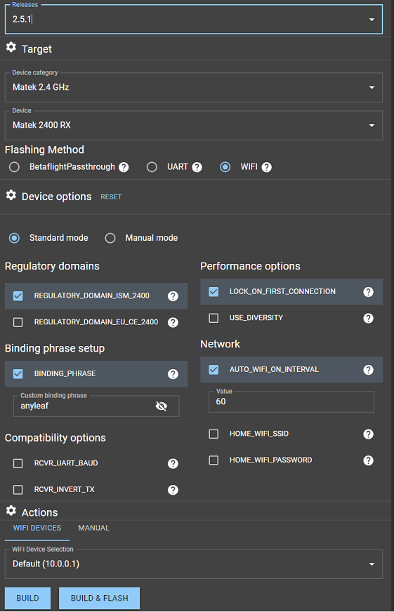
To flash with WiFi after you've built the ELRS firmware, plug in your ELRS module; wait until its LED flashes rapidly. Then search for a WiFi network called ExpressLRS on a WiFi-enabled PC. Connect to this; a browser window should automatically open, displaying a that allows you to select a file, and flash it. Note that some ELRS modules have tiny WiFi antennas, and therefore must be placed close to the PC. This interface can also be used to change the binding phrase.
You should do this on new modules, and when you want to change settings or update ELRS. Keep this version in sync with the Rx module.
This step may be straightforward or a pain, depending on the module, and current alignment of the celestial spheres. If you run into trouble, ask for help on Discord. (Link at the bottom)
ELRS is compatible with controllers that run OpenTx and EdgeTx. You can use this to change ELRS transmitter settings using your controller's UI. To set up the controller (note: This is separate from the above Tx steps!), follow the instructions here to install a LUA script on your controller, and use it. Installation involves using Configurator to download a LUA file, connecting the controller's SD card to your PC, and placing the LUA file in the appropriate directory on the SD.
For example, here's how to access settings on EdgeTx, eg TX16 or Zorro:
The article above goes into detail on these settings, describes what each does, and shows screenshots. After installed, using your controller's UI, you can change settings. I'd like to go over 3 settings in particular that you may wish to confirm or change:
Set this to Wide to take advantage of improved aux (switch) channel capabilities. The other setting, Hybrid, can be considered deprecated.
This setting is the maximum transmit power used. If Dynamic power is off, this is the power the Tx always operates at. With Dynamic on, this is the upper limit.
This is under the Tx Power sub-menu. It defaults to Off. In this setting, whatever you have Max Power set to (on the same menu) will be the constant power. Enabling Dynamic power lets transmitter use the minimum power required to maintain a strong link, and the flexibility to scale up as required, preventing signal (And therefore potentially aircraft) loss.
Note that this setting is particularly useful for increasing flight range (It may default to the lowest setting, for example), but might get you in trouble with regulatory bodies like the FCC! If you're not worried about keeping the Feds off your back, set Dynamic transmit power, and raise the power level.
See this docs article for details on dynamic power. If this is disabled, the power setting will be fixed at Max power. With Dynamic enabled, power will scale between 10mW, and this setting, depending on signal-to-noise ratio (SNR).
You can also use this page to change the telemetry ratio (Telem Ratio setting). This changes how often the Rx sends link quality data back to the transmitter. The value selected corresponds to how often the Rx module sends telemetry packets to the Tx module. For example, a ratio of 1:128 will send a telemetry packet once every 128 control packets. This page has detailed info on packet rate and data bandwidth at various settings.
Note that you also need to configure channels on your controller appropriately for ELRS. For example, in EdgeTx, press the MDL button. Select the MIXES page using the page buttons. Set up your Aileron, Elevator, Throttle, and Rudder controls to channels 1-4. (The order doesn't matter directly, but must match what you have configured in your FC firmware.) Make sure that Channel 5 is set up as whatever switch you'd like to use for arming - ideally a 2-position switch. This is an ELRS requirement: Your arm switch must be set to channel 5.
Updating and configuring the Rx module is the same process as the Tx module. (But make sure to select your Rx module instead of Tx module in the Configurator)
Your FC firmware (Betaflight, iNav, Ardupilot etc) needs to be set up to receive crossfire on the UART port the ELRS Rx module is connected to. It needs to have the correct channels bound to the functions you want (eg Roll, pitch, yaw, throttle for channels 1-4 respectively), and the correct aux channels for arming, control mode etc.
To receive RSSI and link quality and display on OSD (This is important, especially for long-range flights), make sure to select CRSF channels 10 and 11 for RSSI, and link quality respectively.
Here's a secreenshot from Betaflight 4.3.0, demonstrating settings on the Receiver tab:
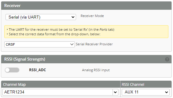
Note that in this case, we've set "RSSI" to channel 11, which is actually link-quality; if using DJI Vtx, you can only use one at a time. Set it to channel 10 to show RSSI instead.
This screenshot, demonstrate choosing the correct UART port on the Ports tab:

Some flight-controllers (FCs) - especially one designed for small quads (whoops etc) have their ELRS circuit built-onto the FC circuit board. They saves space, and is simpler compared to wiring and mounting a separate receiver board. The come in 2 categories:
Flight controllers with a dedicated ELRS MCU work just like ones with a separate Rx - other than not having to connect external hardware. They have an onboard MCU that runs official ELRS firmware, and communicates with the main MCU over a UART line. They run official ELRS software, and are configured and updated in the same way. They're a convenient alternative to separate hardware with no difference in usage; we'll say no more about them.
ELRS-capable FCs without dedicated ELRS MCUs are referred to as SPI or direct ELRS. These connect the RF chip directly to the FC's MCU. Th name SPI is used because that's the protocol the RF chip uses. This name is misleading, because ELRS always uses SPI. In this case, the RF chip uses SPI to connect to the FC's MCU instead of through an ELRS MCU.
SPI ELRS flight controllers don't use official ELRS firmware; part of the FC's firmware (eg Betaflight) is dedicated to running ELRS. This has the advantage of saving board space and cost by not having a dedicated ELRS MCU. It also reduces latency by eliminating steps in the communication chain.
The downside of SPI ELRS , is that it's dependent on FC firmware faithfully implementing the ELRS standard, and keeping it updated with official ELRS releases. (And official ELRS updates frequently!) It also adds tasks to the FC's scheduler, which can cause latency in other places, and may be too much for slower FCs to handle. Betaflight's release cycle is much slower than, and not in sync with ELRS'; it's unclear what support will be like in the future, and if/when a given ELRS feature will be ported to BF. It's also unlikely that other firmware will ever support SPI ELRS.
This Joshua Bardwell video describes this approach in detail. He discusses specific pain points that arise from relying on Betaflight firmware for ELRS.
There are a few features some ELRS Rx units have. Details are available on the official Receiver Selection page. These are all optional, and are mainly useful for long-range use. Here are the most common ones.
Of these add-on features, diversity is the most useful. It allows connection to 2 antennas, via an RF switch. The Rx uses whichever antennas is receiving a stronger signal at a given time. This lets you position antennas on different parts of your aircraft, or at different (eg orthogonal) angles, so that signal strength stays consistent through maneuvers.
This is a variant on Diversity that may be available in future receivers. Instead of using a single radio chip connected to 2 antennas, it uses 2 independent RF chips, each with its own antenna. This is more expensive than normal Diversity, but makes more effective use of dual-antenna setups. Since this form of Diversity receives packets from both antennas simultaneously, it's able to pick up packets picked up on one radio but not the other. In comparison, single-radio diversity must sample each antenna, and makes a (not always correct) guess about which antenna is receiving the better signal. The AnyLeaf dual-radio Rx is an example of a true-diversity receiver. Others include the HappyModel EP1, and the BetaFPV SuperD.
This WIP functionality uses dual ~2.4GHz radios on both the transmitter and receiver. The radios transmit at slightly different (40Mhz difference) frequencies, which provides a more interference-resistant signal that may be useful for racing. Gemini is compatible with all dual 2.4Ghz-radio Rxs.
A power amplifier is included in some Rx modules. It increases strength of telemetry signals sent back to the transmitter. This can be useful for long-range flights. Telemetry (signal-strength data going from the Rx to Tx) is important if your transmitter is equipped with dynamic power adjustment.
A low-noise amplifier is included in some Rx modules; it amplifies the received signal. Note that this also amplifies noise; Gain is generally ~12dBm. This may or may not be useful.
CAN (Controller Area Network) is an increasingly-popular communications protocol for small unmanned aircraft systems. It's ubiquitous in cars and trucks. CAN is a bus that uses differential signals; this simplifies wiring, and provides capability for long signal wires (eg compared to UART). It allows offloading computation power to dedicated computers, and provides robust system status information. The AnyLeaf CAN ELRS device is a 2.4Ghz CAN ELRS module.
The basic status of ELRS receivers can be assessed using their onboard LED. These come in two varieties: Monochrome LEDs that indicate status through flash and blink pattern, and color LEDs, which also use color, and are more expressive. Currently, only dual-radio receivers use RGB indications. This ELRS quickstart page describes LED status indications in detail. Below is a summary:
Monochrome (generally red) LED status
Color (aka RGB) LED status
Here are some considerations to maximize flight range:
This official article goes into detail about considerations for long-range flight. It also includes data points taken by users of range achieved in various configurations.
This video, from January 2023, shows several ELRS team members conducting a flight of 100km! It uses 2.4Ghz. The link holds for the entire flight.
ELRS receivers are capable of transmitting specific telemetry data from a receiver aboard the aircraft back to the control station. (Data about aircraft parameters, not including link statistics) This data includes, for example, barometric altitude, and GPS positioning data if available. This is good enough for many cases, but the exciting possibility exists for ELRS to send arbitrary data for use in custom hardware and advanced projects.
Airport is a work-in-progress firmware replacement for an ELRS Tx and Rx pair that allows it to send arbitrary data using the RF packets normally reserved for control data. This allows custom vehicle or firmware designers to pass whatever information is suitable for their design over the air, without needing to program a radio protocol. Developers can serialize whatever information they want (bandwidth permitting) as binary data, leverage ELRS for the transmission and reception, and receive the binary data on the other side. This could be used, for example, to pass information from vehicle sensors that aren't part of the fixed set of telemetry ELRS normally supports.
Airport requires a dedicated Tx / Rx pair. For example, it may need a Tx on the ground, and Rx in the air to pass control data, and an addition pair: a Tx in the air and Rx on the ground to pass custom telemetry from the aircraft.
Discord The ELRS discord is very active; it's filled with ELRS users, firmware developers, hardware developers, and drone engineers. Beyond ELRS, it has higher-quality drone chat than other mediums.
Github The ELRS Github is a good place to report bugs, request features, or add them.
For hardware examples, check out the ExpressLRS hardware repo. We've also published our own hardware for AnyLeaf receivers.
Overall, ELRS represents everything open-source software design should be. It's a (somewhat) rare example of outperforming proprietary alternatives. It allows enthusiasts to focus on flying, and developers to focus on things other than RF design.