Microcontrollers (MCUs) are ubiquitous in modern electronics. These combination hardware/software devices are called embedded devices, and their software is usually programmed in C or C++. Rust is a modern language that's recently become a viable alternative. This article explores Rust's capabilities on embedded, and provides a starting point for writing firmware with it. It contains introductory information about embedded programming and Rust that you may already be familiar with; you may wish to scroll down and skip to the code examples.
This doesn't intend to be a tutorial, or suitable learning resource on its own. Its goals: Describe why you should consider Rust for new projects, provide an overview of common libraries, and provide code samples that cover the most important parts. Some topics overlap with the official Rust embedded and Rust embedded discovery books. These are great resources for getting started, and go into detail for experienced embedded engineers new to Rust, and people new to embedded respectively. This article's focus is on the architecture of practical firmware, and it describes tools and libraries that have been released after these books.
We wrote the Water Monitor firmware and Stove Thermometer using Rust, and plan to do the same for future devices, due to its memory safety and ergonomics.
For a guide on using Rust in low-level domains like embedded, targetted at C engineers, check out Learn Rust the Dangerous Way. For a categorized list of tools and libraries, check out our article on the topic.
C is the industry standard for embedded programming, and most embedded jobs use C, with a minority using C++. Hiring programmers proficient in Rust is much more difficult than in C or C++ due to the smaller user base. Example code, tools, and libraries released by MCU manufacturers are almost always for C or C++. The Rust embedded infrastructure is new, and rapidly changing.
Currently Rust on embedded works best with ARM Cortex-M-based MCUs. This includes STM32, Nordic MCUs, and the Raspberry Pi Pico. This is changing quickly: Support for Espressif/ESP-32 and RISC-V support are rapidly improving.
High-level library support is immature. Depending on your MCU, you may need to write your own abstractions, or work at the register level. This requires an understanding of the specific hardware capabilities and register layout, requires frequent reference manual (RM) checks, and makes switching MCUs more difficult. Some libraries make heavy use of generics and other verbose syntax.
The Lindy Effect: A phenomenon by which the future life expectancy of some things, like a technology or an idea, is proportional to their current age. If your project has a requirement that the tools used to build and flash your program be available in 10 or 20 years, C may be a better choice: It's long history (arguably) predicts a long future. This is a simplistic outlook, but often works.
Rust is a comparatively new language. It's learned from mistakes of existing languages, and has drawn inspiration from other languages, including C, C++, OCaml, and Haskell. It's one of a handful of languages capable of writing fast, low-level code: the type used to write drivers, operating systems, and embedded firmware. At this time, Rust is one of few viable alternatives to C and C++ in these domains. (Other alternatives include ADA, SPARK, and Zig.) Advantages of using Rust fall into two broad categories: memory management, and ergonomics.
Regarding memory management, most languages fall into one of 2 broad categories: Manually managed, and garbage-collected. C and C++ are examples of manually managed, and Python, Go, and Java are examples of garbage-collected languages. Languages with memory management run quickly, but care must be taken to prevent subtle errors. This Wikipedia article provides a overview of this class of error, and specific examples. Garbage-collected languages don't have this problem, but run comparatively slowly, and with inconsistent performance; they're not suitable for embedded.
Rust has a unique feature: It can run with the speed and fine control of manually managed, but can guarantee memory safety by using a borrow checker to validate references. This forces you to write programs in a memory-safe way; if you make a mistake, it's caught at compile time. Rust's ownership model is responsible for this. From that docs page: "Memory is managed through a system of ownership with a set of rules that the compiler checks at compile time. None of the ownership features slow down your program while it’s running."
In embedded, we often have to bypass Rust's ownership model to interact with hardware. This is confined to blocks marked as unsafe{ }. By carefully controlling code in these blocks and minimizing their use, we can write safe firmware. Rust's ownership model provides the biggest advantages when the heap is used, eg on PCs. On embedded, it's still useful for preventing concurrent access to the same memory. This can occur due to interrupt, DMA use, or additional cores attempting to access the same piece of memory (Eg a buffer, or peripheral register).
Memory management is perhaps the most common reason people consider Rust. In embedded, ergonomics may be an even more compelling reason. Stated simply: Rust programs are (subjectively) easier to read and write. Compiling and flashing embedded C/++ firmware often requires complex tooling, and proprietary and/or expensive IDEs. Development may be tied to an IDE that allows access to MCU-specific features, at the cost of deficiencies as a code editor. Here are some features Rust provides:
Namespaced modules and imports make a big difference to code reading, writing, and maintenance.
Together, these make programming in Rust (including installation, setup, and config) a streamlined process. Rust has a reputation as a challenging, complex language due its its ownership model. Its official tooling, standards, and language features more than overcome this.
The next few sections of this article go over examples of programming an MCU using Rust, at various levels of abstraction. The official Rust embedded book provides more detailed information along these lines. It's a great resource for learning how to use embedded Rust, for those already familiar with embedded programming in C or C++.
In this article, we'll assume you're using an STM32. Most of the information here can be easily modified to work with other ARM Cortex-M processors. The general concepts will work with other architectures as well. The specific variant of STM32 doesn't matter much for the purpose of this article, and the code could be applied to any, with slight modifications.
Interaction with MCUs is usually done using memory mapped peripherals. This means that to interact with an MCU peripheral (or an external one through an MCU communications protocol), you write to, or read from a memory address. This is an important concept: It illuminates the border between abstract computer logic, and interactions with the real world. The code examples below all do this; first directly, then through calling functions and methods that perform these writes and reads.
The most notable restrictions when programming Rust for an embedded target are the lack of a memory heap or allocator by default, and a more limited standard library. To indicated that your Rust program is intended to embedded, put this line towards the top of Cargo.toml: #![no_std]. When this is specified, you must use the Core library instead of the Standard library. For supported features, use core:: as the use syntax, instead of std::. Core is a subset of Standard, and its docs pages for shared features are identical.
Additionally, by default, the heap isn't available. In fact, there's no allocator, which means dynamic memory allocation (Like with Vec and HashMap) won't work. You can use the alloc-cortex-m library if you wish to use an allocator. Alternatively, the heapless library allows use of data structures similar to Vec etc, without using a Heap. Instead, you specify their maximum size at initialization.
Without a stack or allocator, you might pass mutable array references as function parameters, in cases where you'd otherwise return a Vec. Instead of generating a return Vec or array, the function modifies the output reference in-place. In general, you'll make frequent use of (fixed-size) arrays.
rustup target add thumbv7em-none-eabihf.cargo install flip-link, cargo install probe-run. Note that you can also use OpenOCD, although we think Knurling's tools here are easier to use.git clone https://github.com/David-OConnor/stm32-hal-quickstart. Note that this is a thin wrapper over the Knurling App Template. The specific Hardware Abstraction Layer (HAL) library used here will help with our higher-level examples, but makes no difference for our first few.Alternatively, you can create a new project using cargo new --lib projectname, and add the required code. An advantage of using a template like above is it provides some boilerplate needed to work with Embedded, like .config.TOML to specify the compiler target, and memory.x to specify your MCU's amount of flash and RAM. It's likely you'll end up with your own template or templates tailored to your specific use case or MCU.
The main program code lives in src/main.rs. It includes setup code to make your program work with the Knurling debug and flash tools, and example imports for the high-level API we'll use later in this article.
You don't need a special IDE to write and flash embedded using Rust: You can write in your code editor of choice, and use a terminal to compile and flash your code (run cargo run --release). The IntelliJ Rust plugin is very nice, and is compatible with any IntelliJ IDE, including CLion and PyCharm. VsCode with the rust-analyzer plugin is another good choice.
When using the setup created above, to compile and flash, run cargo run --release. Or shorthand: cargo r --release. Using release mode takes longer to compile than without, but using non-release-mode firmware can lead to performance and memory problems. Generally, compiling Rust programs takes longer than compiling an equivalent C program. To compile without flashing, run cargo build --release, or cargo b --release.
This works due to the probe-run tool we installed, in conjunction with the .cargo/config.toml file provided in the template. You may need to change the runner and target lines in accordance with your MCU, as described in comments on those lines. Ie, to set the runner, run probe-run --list-chips, and copy+paste yours. Comment in or out the target line associated with your Cortex-M version. For example, thumbv7em-none-eabihf for Cortex-M4, thumbv6m-none-eabi for Cortex-M0 or M0+, and thumbv8m.main-none-eabihf for Cortex-M33. You can remove the hf suffixes if you don't intend to use hardware floats. (Operations on float types without hardware floats enabled will be comparatively slow.)
For flashing finalized firmware for production, you may want to create a standalone binary. One way to do this is with cargo-binutils, which you can install with this command: cargo install cargo-binutils. You can then compile a standalone binary with this command: cargo objcopy --release -- -O binary target/firmware.bin. You can then use a tool like Stm32CubeProgrammer, or dfu-util to flash an MCU. This is also useful if you intend to flash using USB.
To print to the terminal using the setup above, we can use defmt commands like this: defmt::println!("Pin state: {}", pin_state);, or defmt::error!("Oh no!");. For detailed information on debugging capabilities, check out Defmt's official guide.
Your main program logic in this example will live in the project directly created above, under src/main.rs. It uses the Cortex-M library as a backbone, and can perform computations. To interact with the world (input/output) you'll usually use peripherals on your MCU, including General Purpose Input/Output (GPIO) pins, analog-to-digital and digital-to-analog (ADC and DAC) peripherals, and communication protocol peripherals like SPI, I²C, and UART.
We cross the barrier between abstract computer code, and interaction with the world by writing to and reading from memory addresses in our microcontroller. They're listed in your MCU's reference manual (RM) (Or perhaps called Datasheet or Product Specification). On STM32, you need to look in 2 RM sections: the Memory Organization section near the top to find peripheral base addresses, and the register tables (at the end of each peripheral-specific chapter) to find the offset of each register. You can find the register address using an OR (|) operation between the base address and offset.
The following example uses a low-level API that's not practical for application code, and may be confusing to new users. You may wish to go directly to the Writing registers using a Peripheral Access Crate, or High level abstractions sections: They're more practical.
We'll use GPIO pins as an example, since they're easy to work with on STM32. To write to a register using Rust, we use the ptr::write_volatile function. From that docs page: write_volatile "Performs a volatile write of a memory location with the given value without reading or dropping the old value. Volatile operations are intended to act on I/O memory, and are guaranteed to not be elided or reordered by the compiler across other volatile operations." We wrap this call in an unsafe block, because we're bypassing Rust's memory-safety guarantees. This is required here, and won't cause problems unless another process (like an interrupt returning, DMA, or an additional MCU core) attempts to access the same memory location before these operations complete.
The abstractions we'll build in later sections build on top of the read_volatile and write_volatile commands. They'll have a different API, and application code will look different, and have a different structure - but they're ultimately wrapping these same commands and addresses.
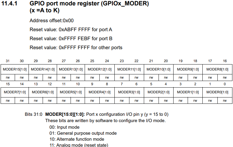
Before we start, here's a table excerpt from the STM32H743 RM, which shows the MODER address offset, what fields are available, and what value each field can take. Note that the GPIOA port base address is listed earlier in the RM - we OR (|) that with the offset listed in the table. Also note that in our code, we use binary and hex notation, even for simple integers, for consistency with the RM. (Technique only! Feel free to us base-10 integers.) Can you see how values in (and above and below) the table correspond to the code below?
This code goes in your main function, which of note, always ends in a loop. (Which is enforced by its ! type signature). We enable our GPIO port's peripheral clock, configure our pins as required, and change and/or read their value. Note that on some MCUs, this process is simpler, and may not required enabling a peripheral clock.
#[entry]
fn main() -> ! {
    // Set up named variables for the register addresses we'll use. These are defined in the STM32's
    // reference manual (RM). You can find base addresses under the Memory and bus architecture chapter, and the offsets (Things we | the base addresses with), under the RCC and GPIO chapters, registers sections.

    let RCC_AHB2ENR = 0x58024400 | 0x0DC;
    let GPIOA_BASE = 0x48001018;

    // You can find these offsets under each RM register table: `Address Offset`
    let GPIOA_MODER = GPIOA_BASE | 0x00;
    let GPIOA_BSRR = GPIOA_BASE | 0x18;
    let GPIOA_IDR = GPIOA_BASE | 0x10;

    let gpioaen_field = 0;
    let output_pin_num = 1;  // A variable to indicate with GPIO pin number we're using. Ie PA1.
    let input_pin_num = 2; // ie PA2.

    unsafe {
        // Set the GPIOAEN field of the RCC register block, AHB2_ENR register. This enables the peripheral clock
        // to all pins on the GPIOA port.
        ptr::write_volatile(RCC_AHB2ENR as *mut u32, 1 << gpioaen_field);

        // Set the mode of PA1 to Output, and PA2 to input. The hex values 0b01 and 0b00 (1 and 0) are defined in the GPIO registers section of the RM, under GPIO port mode register (GPIOx_MODER).
        // We Multiply the pin numbers by 2, since each field of this register is 2 bits wide. Also note that we  perform a register read, as not to override previous settings.

        Let mut existing_val = ptr::read_volatile(GPIOA_MODER as *const u32);
        // We use binary arithmetic here to 0 out the fields we’ll write to. Modifying single-bit fields is simpler.
        existing_val = existing_val & !(0b11 <<  output_pin_num * 2) & !(0b11 <<  input_pin_num * 2)

        ptr::write_volatile(
            GPIOA_MODER as *mut u32,
            existing_val | (0b01 << (output_pin_num * 2)) | (0b00 << (input_pin_num * 2))
        );

        // Write to the GPIOA bit set/reset register. These writes are atomic, so won't experience
        // concurrency issues; no further action is required to ensure safe access across interrupts etc.
        ptr::write_volatile(GPIOA_BSRR as *mut u32, 1 << output_pin_num);

        // Read from the GPIOA Input Data Register, and extract the value associated with PA2.
        let input_state = ptr::read_volatile(GPIOA_IDR as *const u32) | (1 << input_pin_num);
    }
    loop {}
}
The code above is unsuitable for writing firmware directly with. Libraries are available that provide named access to registers and fields. These are conventionally called Peripheral Access Crates (PAC). These are generated from SVD files, as defined in the Cortex-M CMSIS-SVD library. For example, the STM32L4 library provides this for STM32L4 MCUs.
For some peripherals on STM32 like GPIO this is straightforward. For communications protocols, many separate operations are required, so using PACs directly isn't ideal. Other MCUs, like Nordic's nRF series make this easier; their direct register writes are more powerful, while STM32 peripherals rely on recipe-like sections described in their reference manuals. Most peripherals beyond GPIO include more complex config and setup steps, also described in the RMs.
Here's the above GPIO code, written using a PAC. Note that the syntax uses closures. This is to allow changing multiple fields on the same register, without using different syntax.
use stm32l4::pac::{RCC, GPIOA};

#[entry]
fn main() -> ! {
    let mut dp = pac::Peripherals::take().unwrap();

    // Enable the GPIOA peripheral clock as above.
    dp.RCC.ahb2enr.modify(|_, w| w.gpioaen().set_bit());

    // Set PA1 to output, and PA2 to input, as before. Note this simpler syntax that doesn’t
    // require knowing memory addresses. It performs a read, then write, as before, since writing this
    // register overwrites previous bits; that’s what the `modify` method is for.
    dp.GPIOA.moder.modify(|_, w| {
        w.moder1().bits(0b01);
        w.moder2().bits(0b00)
    );

    // The BSRR register is defined as ST as atomic write; you can set a specific bit by
    // writing without performing a read, as `modify` does; this won't affect other bits.
    dp.GPIOA.bsrr.write(|w| w.bits(1 << output_pin_num));

    // Read from the GPIOA Input Data Register, and extract the value associated with PA2.
    let input_state = dp.GPIOA.idr.read().idr2().bit_is_set();

    loop {}
}
As before, compare to the RM table posted above for an example of the registers, fields, and values we're using.
Note how the above code is more concise, doesn't require manually looking up addressed, and doesn't require the unsafe keyword. It's more sustainable in production code, and is similar to Low Level (LL) code APIs in C. An alternative approach is provided in the STM32 Register Access Layer library. This leverages Rust macros to provide a terse syntax.
PACs may or may not be practical for application code, depending on your use case, and how complicated your hardware and peripherals are. They have a distinct advantage compared to other levels of abstraction of mapping directly to RM descriptions.
We'll now use a PAC to implement a series of steps in a RM. In this example, we demonstrate how to configure the UART peripheral in transmission mode. This is intended as a broadly-applicable example of how to set up a peripheral - the same structure and PAC library can be use to set up any peripheral, and similar PACs are available (Or can be built from SVD files) for any ARM MCU:
#[derive(Clone, Copy)]
#[repr(u8)]
/// The number of stop bits to use. Sets the CR2 register, STOP field.
pub enum StopBits {
    /// 1 stop bit
    S1 = 0b00,
    /// Half a stop bit
    S0_5 = 0b01,
    /// 2 stop bits
    S2 = 0b10,
    /// 1 and a half stop bits
    S1_5 = 0b11,
}

// ... The other Config enums are similar.

/// Configuration for Usart. Can be used with default::Default.
pub struct UsartConfig {
    pub word_len: WordLen,
    pub stop_bits: StopBits,
    pub oversampling: OverSampling,
    pub parity: Parity,
}

// ...

/// Set up UART transmission. See STM32L443 RM, section 38.5.2: "Character Transmission Procedures".
pub fn setup_transmission(regs: &mut R, baud: u32, config: UsartConfig, clock_cfg: &Clocks)
    where R: Deref<Target = pac::usart1::RegisterBlock> {

    // 1. Program the M bits in USART_CR1 to define the word length.
    let word_len_bits = config.word_len.bits();
    regs.cr1.modify(|_, w| {
        w.over8().bit(config.oversampling as u8 != 0);
        w.pce().bit(config.parity != Parity::Disabled);
        // M0 and M1 bits are on separate, non-adjacent fields, so we need 2 separate
        // commands to modify them.
        w.m1().bit(word_len_bits.0 != 0);
        w.m0().bit(word_len_bits.1 != 0);
        w.ps().bit(config.parity == Parity::EnabledOdd)
    });

    // 2. Select the desired baud rate using the USART_BRR register.
    set_baud(baud, clock_cfg); // (Setting up the baud rate has its own details!)

    // 3. Program the number of stop bits in USART_CR2.
    regs.cr2.modify(|_, w| w.stop().bits(config.stop_bits as u8));

    // 4. Enable the USART by writing the UE bit in USART_CR1 register to 1.
    regs.cr1.modify(|_, w| w.ue().set_bit());

    // 5. Select DMA enable (DMAT[R]] in USART_CR3 if multibuffer communication is to take
    // place. Configure the DMA register as explained in multibuffer communication.
    // (Handled in `read_dma()` and `write_dma()` functions)

    // 6. Set the TE bit in USART_CR1 to send an idle frame as first transmission.
    regs.cr1.modify(|_, w| w.te().set_bit());
}
This is similar to what STM32-HAL does in its Usart::new constructor. In this case, we've set it up as a standalone function, and have left out a few things like baud-rate and DMA config, as well as all but one config enum, for simplicity. Rust enums are an elegant way to define what possible value each field can take. The value we assign to each variant (in conjunction with the repr(u8) line) matches the bit value from the RM. Note that we use doc comments to show which register and field the enum controls, and copy+paste each value's description from the RM.
In the procedure itself, we cite where in the RM each step came from before we perform it, so it's easy to cross check that the procedure is correct, or identify errors if we encounter problems in use. Using this approach is a viable alternative to a HAL - ie creating your own functions and structs that perform the steps you need. This has the advantage of tighter control over what code your device runs, at the expense of more work upfront - especially if your project requirements change.
Note the line Deref<Target = pac::usart1::RegisterBlock>, and its associated generic parameter R. This is a consequence of how the PACs (and the manufacturer-provided SVDs they're built from) handle similar peripherals. It allows you to use the same code for the USART1, USART2 etc peripherals, instead of tying it to one in particular.
Also note that we perform additional configuration steps under the *Step 1`. These aren't explicitly listed in the RM's transmission procedure, but use the same register - so it makes sense to set them up here, for efficiency, and code simplicity. (The whole register needs to be written even if we only need to change one field.)
For application code, higher-level abstractions are more suitable, but may or may not be available for a given MCU. This is an area that's actively improving in Rust. Our devices are programmed using the STM32-HAL library, which we created for this purpose. It provides a level, ergonomic API for configuring and using peripherals. There are similar libraries available for MCUs, in varying states of robustness and maturity. For example, if you're using a Nordic MCU, check out nrf-RS nRF-HAL. These libraries wrap the PACs with a higher-level, more intuitive API.
Here's an example of it in use. For its full API, check out the STM32-HAL docs.
use stm32_hal2::gpio::{Pin, PinMode, Port};

#[entry]
fn main() -> ! {
    let output_pin = Pin::new(Port::A, 1, PinMode::Output);
    let input_pin = Pin::new(Port::A, 2, PinMode::Input);

    output_pin.set_high();
    let input_state = input_pin.is_high();

    loop {}
}
Note that we don't need to explicitly enable the GPIOA peripheral clock here; the Pin's new constructor handles that, as indicated by its documentation. That page shows other methods available for the Pin struct - these are mostly configuration options for the given GPIO config, and match those listed in the RM. Many of the settings here (and in other modules of this library) use Rust enums to configure. They are set to explicit u8 types associated with their associated bit values. Their You can look at the documentation for the associated enum, or the associated RM entry. For example, here is documentation for the OutputSpeed enum, used with the .output_speed() method.
Now let's look at an example function that takes a measurement from an external ADC, the TI ADS1115. This code is used in the Water Monitor firmware. Note that MCUs like the STM32 usually include onboard ADCs. In this case, we use an offboard ADC, since this particular one provides higher-accuracy readings.
const CFG_REG: u8 = 0x1;
const CONV_REG: u8 = 0x0;

// ...

/// Take a measurement from an external ADS1115 ADC, using the I²C peripheral.
fn take_reading(addr: u8, cmd: u16, i2c: &mut stm32_hal::I2c<I2C1>) -> i16 {
    let mut result_buf: [u8; 2] = [0, 0];

    // Set up the cfg, and command a one-shot reading. Note that we
    // pass the 16-bit i2c command as 2 bytes.
    i2c.write(addr, &[CFG_REG, (cmd >> 8) as u8, cmd as u8]).ok();

    // Wait until the conversion is complete.
    let mut converting = true;
    let mut buf = [0, 0];
    while converting {
        i2c.write_read(addr, &[CFG_REG], &mut buf).ok();
        // First of 16 cfg reg bits is 0 while converting, 1 when ready. (when reading)
        converting = buf[0] >> 7 == 0;
    }

    // Read the result from the conversion register.
    i2c.write_read(addr, &[CONV_REG], &mut result_buf).ok();

    // Convert the 2 8-bit integers from the result into a single 16-bit signed integer.
    i16::from_be_bytes([result_buf[0], result_buf[1]])
}
To understand what's going on here, we need to reference the ADS1115 datasheet linked above. Note that this is a blocking API: The whole program is frozen during the time it takes to perform the conversion (See the while converting loop). For our purpose here, this is acceptable, since we're taking one reading from each ADC at a relatively low frequency. If we needed to perform a sequence of readings, or continuous readings, we'd use interrupts, or even better, DMA, instead of a blocking loop.
Also note that we return an i16: A signed integer, since this is a differential reading. Note that the cmd command argument configures the ADC, and takes a reading, IOC the ADC's datasheet. Also note that both reading and writing is performed 8 bits at a time, IOC the I2C protocol, and the ADC's datasheet.
The .ok() suffixes are due to the I2C read and write methods having the potential to return an error state generally, although we don't expect to encounter that here. Note the write_dma and read_dma methods also available on that page.
If you examine the function signature, you'll see this line: i2c: &mut I2c<I2C1>, in addition to the I2C device address and command we're sending. This is a mutable reference to the HAL library's I2c struct. We can see from that page that we initialize it with its new constructor. Included also is our clock setup boilerplate, initializing to a safe default that varies based on the MCU used:
let clock_cfg = Clocks::default();
clock_cfg.setup().unwrap();

let i2c = I2c::new(dp.I2C1, Default::default(), &clock_cfg);

// ...

let reading = take_reading(PH_ADC_ADDR, PH_READ_CMD, &mut i2c);
This initializes the I2C peripheral with default settings, since we replace the cfg parameter with its default implementation. To see what other configuration options are available, you can view the I2cConfig's docs page. Here's an example config that modifies the noise filter and speed settings of the default config:
let i2c_cfg = I2cConfig {
    speed: I2cSpeed::Fast400K, // Set to Fast mode, at 400Khz.
    // Set a digital noise filter instead of the default analog one.
    noise_filter: NoiseFilter::Digitial(5),
    ..Default::default()
};
The first argument to I2c::new is the PAC structure that allows (exclusive-by-default) access to modify the registers. This helps to prevent race conditions. The second argument indicates which of the several I2C peripherals is being used - lets the library know which peripheral clock to enable. The final &clock_cfg argument passes information about how the MCU's clocks are configured, so it can properly set the I2C peripheral's speed using scalers.
This peripheral configuration is specific to STM32's I²C using the STM32-HAL library, but can be applied more broadly: All peripherals in this library use the same basic API. Other HAL libraries use different syntax, but accomplish the same basic tasks.
On STM32, you need to configure pins associated with a peripheral with the suitable alternate function. Other MCUs often require a similar process. For example, nRF MCUs require setting the peripherals PSEL register to identify the pins used. I²c generally also requires SDA and SCL lines to be pulled high, and set as open drain. On many variants, pins PB6 and PB7 can be used as SCL and SDA pins respectively, when set as Alternate Function 4. (Check your MCU's user manual for this information; on STM MCUs, this is separate from the RM, and is more specific). Given the example GPIO code above, and the STM32-HAL GPIO Pin docs, can you figure out how to set up the pins? You need to set the alternate mode, make them pullup using software, and configure as open drain. You can use any of the 3 APIs above. The HAL code will be the most concise, and can be determined using that docs page alone.
In practice, much of embedded application code occurs in interrupts, which call functions called Interrupt Service Routines (ISR) when specific events occur. These pause other code as required to run. ISRs can also interrupt other ISRs of lower priority.
The code above include an empty loop at the end of their main functions. This causes continual power use from the MCU. In order to prevent this, you can use the Cortex-M wait for interrupt (WFI) instruction. This causes the MCU core to enter a low power mode until an interrupt occurs. You can do this by adding this code instead:
use cortex_m::asm::wfi;

// ...
#[entry]
fn main() -> ! {
    // ...
    loop {
        wfi(); // use `asm::nop` instead, if you do not wish to put the MCU in a low-power mode.
    }
}
Different MCUs handle low power modes in different ways, but this often enters a basic low power mode. On STM32, by default, this configures a mode called sleep, or sleep now. You can also use the STM32-HAL function low_power::sleep_now(), which ensures the appropriate configuration is set, then enters WFI. (In case you'd previously set it to go into a deeper low power mode upon wfi.)
Interrupts pause execution of other code (such as the main loop), in order to run specific code. They can be triggered by various events, including timers expiring, ADC conversions being ready, FIFO buffers for various peripherals being filled, errors occurring etc. The specifics depend on the MCU. T
To enable a specific interrupt, it usually needs to be configured by the peripheral. In addition, it needs to be unmasked, eg using the Cortex-M NVIC system. The following excerpt shows how to unmask an interrupt, and set its priority, using the cortex-m library. This should go in your main function, above the infinite loop. You may need to place this right above the main loop, to prevent ISRs from running before you initialize peripherals and state.
unsafe {
    NVIC::unmask(pac::Interrupt::TIM2);
    cp.NVIC.set_priority(pac::Interrupt::TIM2, 1);
}
Note that lower-valued priority values have a "higher" priority. When an interrupt occurs, an Interrupt Service Routine (ISR) runs - this is a type of function.
#[interrupt]
/// This ISR runs when Timer 2 expires.
fn TIM2() {
    // You may need to clear an interrupt flag here, depending on MCU and peripheral.
    defmt::println!("Timer 2 expired!");
}
The above code is agnostic to any Cortex-M MCU, while the code that configures a given peripheral to generate an interrupt depends on the MCU and peripheral. Note that you may need to clear an interrupt flag in the ISR depending on the peripheral, or the ISR will continuously run. Here's an example of setting up a timer and its interrupt, using STM32-HAL:
let mut debounce_timer = Timer::new_tim2(dp.TIM12, 10., &clock_cfg);
debounce_timer.enable_interrupt(TimerInterrupt::Update);
This enables Timer 2, sets it to repeatedly count down with frequency of 10Hz. (0.1s period), The timer triggers an interrupt each time it counts down. This means the associated ISR will run 10 times each second.
If an interrupt of higher priority triggers while this ISR is running, this ISR will pause execution until the higher-priority interrupt's ISR completes, then resume where it left off. (Note that any interrupt will pause the main loop's code until it completes). If a lower or equal priority interrupt triggers, this ISR will complete first, then the new interrupt's ISR will run.
Interrupts can be used to wake up devices from low power states. The specific depends on your MCU, and the low power state being used. Battery-powered devices often run in a low power mode by default, periodically wake up to run an ISR, then go back to the low power mode. Lighter low power modes (Like sleep on STM32) are fast to enter and exit, and are easy to use. Deeper states like stop and standby take longer to exit from, may require re-configuring peripherals like clocks, and may not preserve RAM contents.
Direct Memory Access (DMA) allows peripherals to communicate with each other, and with memory without direct intervention from the CPU. They can perform tasks that could also be done with ISRs, but without interrupting other code execution. This is very useful for performance-critical, and low-power applications. It's especially useful when sending or receiving large buffers of data.
Examples of when you may want to use DMA
With DMA, you can initiate a transfer to or from an array, then do other tasks without waiting for the transfer to complete.
DMA has the potential to cause concurrency problems. For example, let's say you pass a (pointer to a) array to be updated by a peripheral using DMA. DMA by nature runs simultaneously with other code - that's one of its big advantages. If you modify the buffer before the write completes, or drop it from memory, you may get undefined behavior, or a crash. Here's an example of code using DMA to trigger a DAC write from a buffer. We use a timer to trigger the writes:
    let mut dac_timer = Timer::new_tim6(dp.TIM6, timer_freq, &clock_cfg);

    //  The update event is selected as a trigger output (TRGO). For instance a
    // master timer can then be used as a prescaler for a slave timer.
    dac_timer.set_master_mode(MasterMode::Update);

    let mut dac = Dac::new(dp.DAC, DacBits::TwelveR, 3.3);
    dac.set_trigger(DacChannel::C1, Trigger::Tim6);

    let mut dma = Dma::new(dp.DMA1);

    dma::mux(DmaPeriph::Dma1, DmaChannel::C3, DmaInput::DacCh1, &mut dp.DMAMUX1);

    // Load the Sine LUT into a DMA circular buffer, which will send a 16-byte word of data
    // to the DAC on each timer trigger. Because it's a circular buffer, it will start at
    // the first value again once complete.
    let channel_cfg = dma::ChannelCfg {
        circular: dma::Circular::Enabled,
        ..Default::default()
    };

    unsafe {
        dac.write_dma(
            &SIN_X,
            DacChannel::C1,
            DmaChannel::C3,
            channel_cfg,
            &mut dma,
        );
    }

    dac.enable(DacChannel::C1);
    dac_timer.enable();
This code sends a word from the SIN_X array to the DAC every time Timer 6 expires. When it reaches the end of the array, it starts again at the beginning. In this case, we've defined our buffer as a static variable. Let's say instead, this code were in a function, and we'd used a local variable for the buffer. The buffer would dissapear when the function finished running, but the DMA peripheral would continue to attempt to access that memory location, leading to undefined behavior, or crashes.
Another way we can get into trouble with DMA is setting the DMA to write to a mutable buffer, then manually modifying that buffer before the write completes.
The embedded-dma library provides Traits that attempt to provide memory-safe interfaces for DMA. When used properly, these should guarantee race-free DMA use. I don't know if there is a good reference implementation at this time.
Concurrency can lead to state variables, memory-buffers, and other data structures being requested by multiple segments of code at arbitrary times. If more than one piece of code attempts to access the same resource simultaneously, undefined behavior can occur. There are several ways we can deal with this.
From the Rust documentation on Atomic types: "Atomic types provide primitive shared-memory communication between threads, and are the building blocks of other concurrent types." These work the same as atomics in other languages, and their ordering system is the same as C++'s.
Bottom line: using atomic types is slightly verbose and has subtleties (beyond the scope of this article), but is the best way to safely share integers and booleans between contexts. They're not suitable for more complicated types like structs.
use core::sync::atomic::{AtomicBool, Ordering};

static READY: AtomicBool = AtomicBool::new(false);

// ..

    let ready = READY.load(Ordering::Acquire) {

    READY.store(true, Ordering::Release);
Atomic types have a number of methods that allow various forms of safe manipulation. Here are the docs for AtomicBool and AtomicU8. These can be tricky to learn, but should be your default way of handling mutable global integers and booleans. Unlike Mutexes below, they don't require critical sections.
For managing access to resources that don't have atomic types (eg structs, like the ones we used to manage peripherals above), we can use Mutexes to ensure only one resource has access at a time. Two Cortex-M features are useful here: mutex and Critical sections. Note that this is different from the mutex in Rust's standard library.
A mutex, short for Mutual Exclusion, can be thought of as a lock, preventing access to the resource under normal circumstances. This Wikipedia article goes into detail. No interrupts are allowed to interfere with critical sections - mutexes can be accessed in these. Combined, they allow for exclusive access to the resource: only one process can be in the critical section at a time. We also need to use Rust's RefCell or Cell in conjunction with the mutexes.
How it works:
Mutex<RefCell<Option<type>>>, where type is the type in question. Option is required, since we need to initialize this with a value, but often can't set up the variable we're storing until the main function. Option allows us to initialize it to None.main, replace the interior of this type with our actual variable. Note that we use cortex_m::interrupt::free to start a critical section. Everything inside of its closure runs without being interrupted.Note that for Copy types, we use Cell instead of RefCell, and don't need the option. Example:
// `RefCell<Option>` For non-copy types
static ADC: Mutex<RefCell<Option<ADC<ADC1>>>> = Mutex::new(RefCell::new(None));
// `Cell` for copy types
static SENSOR_READING: Mutex<Cell<f32>> = Mutex::new(Cell::new(335.));

#[entry]
fn main() -> ! {
    // ...
    let mut adc = Adc::new_adc1(dp.ADC1, Default::default(), &clock_cfg);

    // Set up a GPIO pin associate with a button that grounds the pin when pressed.
    let mut read_button = Pin::new(Port::A, 0, PinMode::Input);
    read_button.pull(Pull::Up);
    read_button.enable_interrupt(Edge::Falling);

    // Set up our ADC as a global variable accessible in interrupts, now that it's initialized.
    free(|cs| {
        ADC.borrow(cs).replace(Some(adc));
    });

    // Unmask the interrupt line. EXTI0 is used for GPIO interrupts, eg when pushing a button.
    unsafe {
        NVIC::unmask(pac::Interrupt::EXTI0);
        cp.NVIC.set_priority(pac::Interrupt::EXTI0, 0);
    }

    loop {}
}

#[interrupt]
/// GPIO interrupt associated with pins numbered 0 (PA0, PB0 etc)
fn EXTI0() {
    unsafe {
        // Clear the interrupt flag, to prevent continous firing.
        (*pac::EXTI::ptr()).pr1.modify(|_, w| w.pr0().set_bit());
    }

    free(|cs| {
        // We use this syntax, inside a critical section, to access our Adc struct, as a mutable reference.
        let mut a = ADC.borrow(cs).borrow_mut();
        let adc = a.as_mut().unwrap();

        let reading = adc.read(AdcChannel::C1).unwrap();
        SENSOR_READING.borrow(cs).replace(reading);

        // This is how we get the value using the `Cell` syntax.
        let reading2 = SENSOR_READING.borrow(cs).get();
    });
}
Unfortunately, this is verbose. You can make it easier using macros to simplify the syntax. The STM32-HAL crate includes some for this purpose. For example, you can use let adc = access_global!(ADC, adc, cs); instead of the 2 lines above. It also contains a macro for the initialization, which makes the syntax more concise. Note that the code above relating to reading and writing these Mutex variables use the cs parameter from free's closure. This is an indication they need to be in a critical section to run.
Critical sections and mutexes have a disadvantage: No interrupts can occur inside them. This includes higher-priority ones, which would otherwise run inside lower priority ones. This is not a problem for some uses, but can be a deal breaker for processes that need to respond quickly, like RF and USB. See the below section on RTIC for one way around this. You should try to keep critical sections short, so interrupts are delayed for the shortest time possible.
The Real-Time Interrupt-driven Concurrency library is a lightweight framework that uses static analysis to ensure safe state access between contexts. It performs checks at compile time to ensure race conditions don't happen, and is built on top of Cortex-M's interrupt system. RTIC requires you to structure your program in a specific way. Note that this a drop-in replacement for some other methods of handling concurrency. For example, RTIC Tasks can be thought of as ISRs with a different syntax, and its task priorities are similar to the NVIC peripheral it wraps.
RTIC has a distinct advantage for resource sharing over critical sections (CS): CSs prevent any interrupt from occuring until they complete. RTIC can higher-priority interrupts to execute inside their CS-analog: The lock. This is allowed as long as the higher-priority interrupt doesn't use a resource controlled by the lock it executes inside.
RTIC also provides a scheduling abstraction using hardware timers, called monotonic. It's able to use a timer to schedule a task (RTIC's name for interrupt handler) to run at a certain time in the future. This can make code easier to reason about, and more generic than using the timers and their associated ISRs directly. It also handles converting timer ticks to time in seconds etc.
The easiest way to learn RTIC is from the documentation above, or from official examples. It's used to solve the same problem we solve above using mutexes and critical sections, and its code structure is similar, although with different syntax.
If you like Async and Await syntax, check out the Embassy project. This provides an alternative control flow to ISRs, which you may be familiar with from Javascript, Python, or non-embedded Rust. There are currently no releases, but it's usable from Github. It uses a custom PAC, which abstracts over differences between MCUs, resulting in simpler HAL-level code.
The Rust embedded working group provides a library called embedded-hal that provides standard interfaces for working with common peripherals. It does this by leveraging Rust's trait system - a form of generics. Its goal is to allow the creation of software libraries that provide a high-level interface to a specific peripheral (eg a display, sensor etc). These libraries can then be used with arbitrary MCUs. The Awesome Embedded Rust page contains links to a number of these libraries.You may not need to write a driver/interface for each peripheral you use - there's a chance someone's already written one, and you can use it as a dependency.
This is a promising idea, and is useful for prototyping. At this time, most of these traits are too limited to be useful, other than for communications protocols like SPI, I²C etc. Many drivers that use them are unsuitable for real-world devices, due to missing features, lack of regard for power use, blocking interfaces, poor ergonomics, or interfaces unsuitable for use with DMA. This may change in the future. If you find an embedded-hal driver for a peripheral you're using, give it a try, and see if it meets your project's requirements - if so, it may save time.
The complete firmware for our conductivity module is published here, in the STM32-HAL examples folder. The ec.rs file included is also directly used by the Water Monitor, as a dependency. This is a simple program that demonstrates how to make embedded firmware using Rust. It manages a DAC, external multiplexer, polarity-switch and I2C ADC to take conductivity measurements. Dive in to the code and comments for more details. src/main.rs contains code for setting up peripherals and control flow. src/ec.rs contains code for preparing measurements, and is used by both the standalone module, and Water Monitor.
For another example, here's the (WIP!) code for the sensor module of our upcoming Stove thermometer. Note that this uses a different HAL library. It's a modified version of the nrf-rs nRF-HAL linked above, with some changes to improve the API. This device periodically takes measurements from an MLX-90614 IR thermometer, transmits them over a simple radio protocol, then goes to sleep until the next measurement. It's designed to run for long periods of time on a coin cell battery.
Zig is another modern language that's suitable for embedded programming. It's a much simpler language, and isn't as strict about memory management as Rust. Its embedded infrastructure is currently small, and its dependency management is a work in progress. Zig may be a good alternative to Rust on embedded in a few years, but isn't suitable for production devices at this time.
If you're looking for a modern language for embedded that's safer and more ergonomic than C, but don't like Rust's complexity and surface-area, Zig may be suitable in the future. This article by Kevin Lynagh compares keyboard firmware written in Rust and Zig.
If you'd like to use a C library in Rust, you can wrap it using the Bindgen tool, which "automatically generates Rust FFI bindings to C (and some C++) libraries." Rust, by design, has basic types that map 1:1 with C types. This makes libraries wrapped with Bindgen compatible using an API compatible to the original, and with automatic conversion. For example, cmsis-dsp-sys is a Rust library built using this tool that wraps the official ARM CMSIS-DSP library. This is a powerful, well-documented library for performing calculations useful for DSP - and its documentation is easy to interpret in Rust. A notable limitation is that since C doesn't use references, the generated Rust APIs use pointers for arrays, leading to syntax different from typical Rust. You can either use this API (making use of an array's .as_ptr() and .as_mut_ptr() methods), or wrap in a higher-level Rust API.
When communicating with embedded engineers who don't use Rust, it's easiest to talk in terms of registers, fields, and other concepts that come directly from RMs and datasheets. For example, you may not be familiar with the official HAL functions commonly used by STM32 users and vice versa, but you both share the language of register reads and writes, which higher level libraries wrap, and documentation refers to.
For example, let's say you're describing setting up an STM32 DAC: A C user may describe the process as running HAL_DAC_Start(&hdac2, DAC1_CHANNEL_1);. You might describe it as hal::Dac::new(dp.DAC, DacBits::TwelveR, 3.3); dac.enable(Channel::C1);. Neither of you would know what the other is talking about! But you both can understand the process described in the RM: (Paraphrased)